
|
|
|
|
|
|
|
|
|
|
||||||||
|
|||||||||
|
Product
Tools, Drivers, etc |
GESBC-9G25wProduct SupportQuick Link
Board Diagram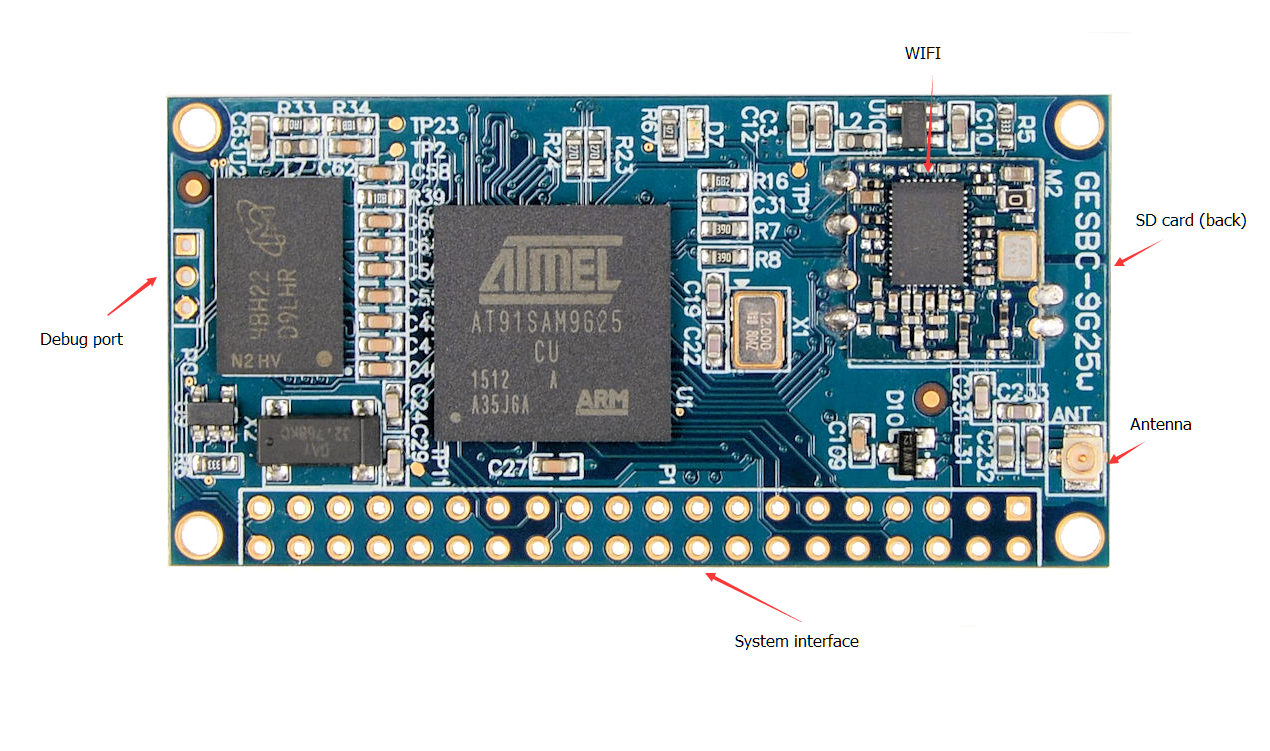
Pre-compiled Binary Images & Source Patches Pre-compiled boot.bin, boot strap code. Pre-compiled Linux 4.5.2 kernel zImage. Pre-compiled boot.bin, boot strap code. Pre-compiled Linux 4.5.2 kernel zImage. Linux 4.5.2 patch for GESBC-9G25w. Linux 4.5.2 kernel device tree configuration binary (DTB) for GESBC-9G25w. Linux kernel device tree configuration source file (DTS) for GESBC-9G25w. pre-built system SD card image. Linux 4.5.2 patch for GESBC-9G25w. Linux 4.5.2 kernel device tree configuration binary (DTB) for GESBC-9G25w. Linux kernel device tree configuration source file (DTS) for GESBC-9G25w. pre-built system SD card image.Debug Serial Port.Similar to many other ARM processors the AT91SAM9G25 processor uses a serial port as a debug port in additional to JTAG port. The factory built Linux kernel uses this port as the system console. The port is marked as P0 on the PCB. It is a 3 pin header with 2mm pin spacing. It connects directly to the CPU so the port is a LVTTL UART. A USB-to-UART adapter can be used to connect desktop system to the GESBC-9G25w. Alternatively a RS-232 driver chip can be used externally to translate the signal voltage to RS-232 level. The pin out of P0 is shown in the following table.
System InterfaceThe GESBC-9G25w connects to external devices and power supply via a 2 x 20 dual row solder pads. It is marked P1 on the GESBC-9G25w PCB. The following table lists main function and alternate function of each pin.
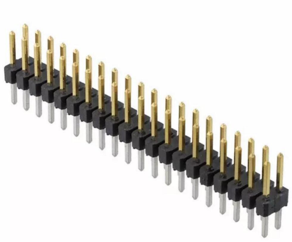
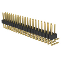
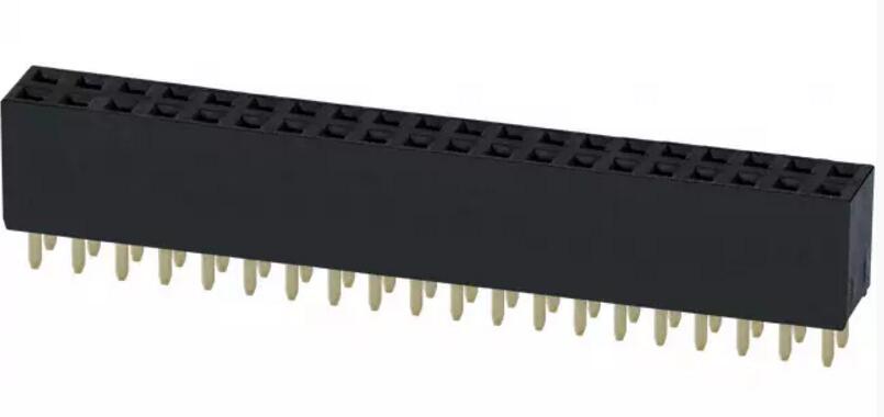
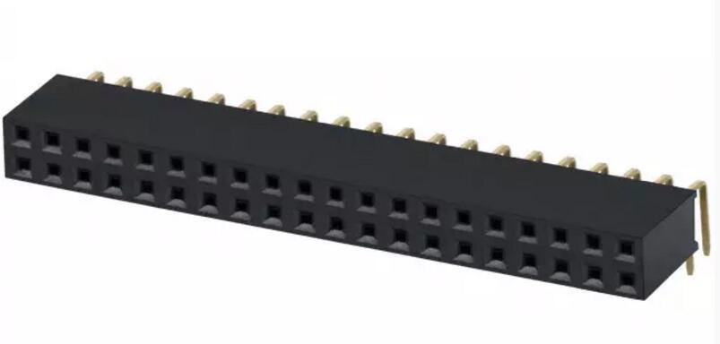
The solder pads use standard 2.54mm spacing. It can accept Standard 2.54mm spacing male headers, female receptacles, both straight and 90 degree angled versions. The connector can be mounted on top side or the bottom side of the PCB. The following pictures demonstrate possible configurations,
I/O Pin ConfigurationMost of the signal lines on P1 can be configured either as GPIO or its alternate peripheral function(s). The Linux 4.5.2 kernel uses device tree to configure the functionality of the GPIO line(s). The factory built device tree has the following peripheral functions configured,
factory device tree source file for GESBC-9G25wCreating Bootable SD cardThe GESBC-9G25w is designed to use micro SD card as the boot media as well as the storage for root file system. The SD card should be partitioned into a FAT partition and a Linux compatible partition, e.g. ext3, ext4, etc. The FAT partition should be the first partition and must be set as bootable. A 20MB FAT partition should be sufficient since the files must be stored in the FAT partition are Linux kernel,device tree binary, and boot strap code. The remaining storage space can be all assigned to Linux file system. A pre-built SD card image is available for download. The WinDiskImager utility can be used to write the pre-built disk image file. Although the image was built on a 1GB SD card the WinDiskImager can smartly write to SD cards with bigger capacity. Linux fdisk or sfdisk utility can also be used to manually partition the SD card. Once the SD card is partitioned mount both the FAT and Linux partition. Copy boot.bin, gesbc-9g25w-.dtb, and zImage to the FAT partition. Untar the Debian file system to the Linux partition. Please make sure to sync the drive before umounting the partitions. The GESBC-9G25w should boot automatically with the SD card in the socket and 3.3V power supply is applied to the power pins.
System OperationUser and PasswordThe factory SD card image has Debian 8.4 file system installed. It has two users: debain and root. Both account has password disabled. Typing in the user name at the login prompt will get to Linux command prompt. Software PackagesThe factory installed Debian file system has only basic system packages installed. User can use package management tool APT to manage software packages. For example the following command will install gcc compiler,
    apt-get update
    apt-get install gcc
For detailed information on APT please see https://wiki.debian.org/Apt WIFI ConfigurationScan for available networks and get network details:
# iwlist scan
Now edit /etc/network/interfaces. The required configuration is dependent on your particular WIFI network setup. The typical setting is,
          # my wifi device
          auto wlan0
          iface wlan0 inet dhcp
                  wireless-essid [ESSID]
                  wireless-mode [MODE]
For WPA-PSK and WPA2-PSK
          auto wlan0
          iface wlan0 inet dhcp
                  wpa-ssid myssid
                  wpa-psk ccb290fd4fe6b22935cbae31449e050edd02ad44627b16ce0151668f5f53c01b
The psk can be generated from the pass phrase using the following command,
#wpa_passphrase myssid my_very_secret_passphrase
For more detailed information see https://wiki.debian.org/WiFi/HowToUse Power ManagementThe factory installed Linux kernel has power management built-in. It supports three power saving mode, freeze, standby, and mem. The following example shows how to put the system in standby mode, echo standby > /sys/power/state A wake up source should be configured before putting the system into power saving mode. The RTC can be used for timed wake up. RTC module can be setup for predefined alarm timeout and the system wakes up from standby after that amount of time. For RTC Wakeup, use 'rtcwake' command to enter and wakeup from standby. rtcwake -d [RTC device (rtc/rtc0)] -m [suspend mode (mem/standby)] -s [number of seconds] To enter standby and wake up after 5 seconds with rtc0 as rtc device, use below command. rtcwake -d /dev/rtc0 -m standby -s 5 The GPIO pins can also be used to wake up the system but it must be configured in the system device tree. The following section of GPIO node configuration demonstrates how to configure GPIO A11 as wake up source,
      gpio_keys {
            compatible = "gpio-keys";
                pinctrl-names = "default";

            button {
                label = "pb_user1";
                gpios = <&pioA 11 GPIO_ACTIVE_LOW>;
                linux,code = <0x104>;
                wakeup-source;
            };
|