
|
|
|
|
|
|
|
|
|
|
||||||||
|
|||||||||
|
Product
Tools, Drivers, etc |
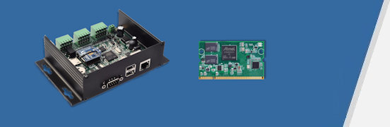
GESBC-9G20iDocumentation GESBC-9G20i User's Manual. GESBC-9G20i User's Manual.
Pre-built Binary Images Pre-compiled boot strap code for standard 32MB SDRAM board. Pre-compiled boot strap code for optional 64MB SDRAM board. Pre-compiled U-Boot image for standard 32MB SDRAM board. Pre-compiled U-Boot image for optional 64MB SDRAM board. Pre-compiled Linux 2.6.35.9 kernel image. Embedded Linux file system JFFS2 image(OABI) based on Emdebian Crush. Pre-compiled WIFI (VNT-6656) driver module for kernel 2.6.35.9. Pre-compiled character LCD display driver module for kernel 2.6.35.9. Pre-compiled boot strap code for standard 32MB SDRAM board. Pre-compiled boot strap code for optional 64MB SDRAM board. Pre-compiled U-Boot image for standard 32MB SDRAM board. Pre-compiled U-Boot image for optional 64MB SDRAM board. Pre-compiled Linux 2.6.35.9 kernel image. Embedded Linux file system JFFS2 image(OABI) based on Emdebian Crush. Pre-compiled WIFI (VNT-6656) driver module for kernel 2.6.35.9. Pre-compiled character LCD display driver module for kernel 2.6.35.9.
Source Code Kernel configuration file for kernel 2.6.35.9. Kernel source patch file for kernel 2.6.35.9. GESBC-9G20i bootstrap code source package
Use the On-Chip 4 Channel 10bit ADCThe ADC driver for the AT91SAM9G20 on-chip ADC exposes the user space interface via sysfs. Below is a simple command line example reading the on-chip ADC, echo "1" > /sys/class/misc/adc/ch0_enable cat /sys/class/misc/adc/ch0_value The ADC input range is 0 ~ 3.3V. The resolution is 10bits.
Control The Digital OutputThere are 6 open collector output ports on the GESBC-9G20i. They are connected as following,
The GPIO driver uses sysfs to interface with user space programs. The control file structure is, #: ls/sys/class/gpio export gpiochip0 gpiochip32 gpiochip96 gpiochip128 gpiochip64 unexport The GPIO pins are grouped into 3 groups on the AT91SAM9G20 processor, PIO-A, PIO-B, PIO-C. The device driver maps pins of each group into GPIO chips and each GPIO pin was assigned a port number. The PIO-A starts from port number 32, the PIO-B starts from port number 64, and the PIO-C starts from 96. To calculate the port number of a specific pin just simply add the pin number in its group to the group base number. For example the PB12 is mapped at port number 64 + 12 = 76. The GPIO output must be exported first before it can be used. The direction also must be set as output as shown in the following example, echo "76" > /sys/class/gpio/export echo "out" > /sys/class/gpio/gpio76/direction echo "1" > /sys/class/gpio/gpio76/value sleep 3 echo "0" > /sys/class/gpio/gpio76/value Please note the GPIO numbering scheme has changed from kernel version 3.6.*. The PIO-A starts from 0 instead of 32 for newer kernels.
Read the Digital Input PortsThe GESBC-9G20i has 8 protected digital input ports configured as following,
The following example demonstrates the basic operation of reading the first digital input port on terminal block J8 on the GESBC-9G20i, echo "112" > /sys/class/gpio/export echo "in" > /sys/class/gpio/gpio112/direction cat < /sys/class/gpio/gpio112/value Please note the port number and direction only needs to be exported and set once.
Sample ProgramsSample C program to control digital output and read digital input on GESBC-9G20i. Sample C program to display messages on a 4 x 20 character LCD display connected to a GESBC-9G20i. Sample RS-485 communication C program to send data through RS-485 port. |