
|
|
|
|
|
|
|
|
|
|
||||||||
|
|||||||||
|
Product
Tools, Drivers, etc |
GESBC-7200Pre-built Binary Images Pre-compiled kernel image. Pre-compiled kernel modules. System device configuration binary file. Pre-compiled kernel image. Pre-compiled kernel modules. System device configuration binary file.
System Diagram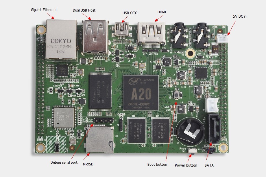
Power ConnectionThe GESBC-7200 requires a 5V DC power supply.
Debug Serial PortThe GESBC-7200 provides a LVTTL level debug serial port to monitor system status
Expansion HeadersThe GESBC-7200 has two 2.00mm spacing expansion headers to provide extensive peripheral functions. Expansion header J2 signal list
Expansion header J3 signal list
Updating System SoftwareThe GESBC-7200 has Lubuntu desktop file system pre-installed. The kernel image and system configuration file can be updated when customized kernel and/or system usage is needed. The following example demonstrates kernel and system configuration updating process, #: mount /dev/nanda /mnt #: cp <source directory>uImage /mnt/uImage #: cp <source directory>script.bin /mnt/script.bin #: umount /mnt
Control GPIOThe GESBC-7200 default system configuration includes 2 GPIO ports, PH17 and PH18. The PH17 is configured as output and PH18 is configured as input in the system configuration. User can change the GPIO direction using sysfs interface. The PH17 is GPIO port 1 in the sysfs interface and PH18 is GPIO port 2. User must first enable the port by exporting the port number to the sysfs interface. User can change the direction of the port using the sysfs interface as well. The following example shows how to enable the port 1 and change its direction. #: echo 1 > /sys/class/gpio/export #: ls /sys/class/gpio export gpio1_ph17 gpiochip1 unexport #: echo 0 > /sys/class/gpio/gpio1_ph17/direction #: cat /sys/class/gpio/gpio2_ph17/value 0 #: |